- Petrocertif Construction Academy Newsletter
- Posts
- HYDRONIC PIPING COOLING SYSTEM BESTS FIELD ENGINEERING PRACTICES FOR DATA CENTERS
HYDRONIC PIPING COOLING SYSTEM BESTS FIELD ENGINEERING PRACTICES FOR DATA CENTERS
Hervé Petrocertif Group
February 22, 2026
FIELD ENGINEERING BEST PRACTICES FOR PERFORMANCE, RELIABILITY AND LONG-TERM RESILIENCE
1. Introduction
The exponential growth of hyperscale and edge data centers has transformed cooling systems from a secondary infrastructure component into a strategic engineering priority. In high-density environments, hydronic piping systems are no longer just distribution networks they are mission-critical assets directly impacting uptime, PUE performance, and operational continuity.
Drawing from field engineering experience in piping systems, ASME B31 codes, process plant layout, and construction project execution, I would like to share structured reflections on best field engineering practices for hydronic piping cooling systems in data center construction.

Engineering Foundation: Code Compliance and Design Integrity
A hydronic cooling network in a data center must be treated as a pressure piping system, not merely mechanical HVAC support.
Best practices begin with:
Strict alignment with ASME B31.1 / B31.3 principles (depending on classification)
Stress analysis considering thermal expansion, vibration, and dynamic loads
Proper material selection (carbon steel, stainless steel, grooved systems, HDPE where applicable)
Welding procedure qualification aligned with project QA/QC plans
Corrosion allowance and water chemistry compatibility
Field reality often reveals that failures do not originate from design errors but from execution gaps between drawings and installation.


Constructability-Driven Layout Strategy
Hydronic piping in data centers is typically dense, multi-layered, and coordinated with electrical busways, fire protection, and structural elements.
Critical field engineering practices include:
3D coordination (Navisworks or BIM-based clash detection)
Defined expansion loop positioning
Accessible isolation valve zoning strategy
Drain and vent optimization for commissioning efficiency
Clear pipe labeling and flow direction marking (critical during maintenance and emergency intervention)
From experience, poor spatial planning increases maintenance downtime more than any other technical factor.


Quality Control: Welding, Testing and Flushing
In data center environments, hydronic contamination is a silent threat.
Best field practices require:
Controlled welding environments
WPS/PQR compliance
NDT (as required by project specs)
Hydrostatic testing with calibrated instrumentation
Chemical flushing and passivation before commissioning
Strict particulate control before chiller/CRAH activation
Improper flushing can reduce heat exchanger performance within months.
Reliability begins at installation.

Commissioning-Oriented Thinking
Engineering does not end at mechanical completion.
The field team must integrate:
Flow balancing verification
Delta-T validation
Pump curve performance checks
Redundancy logic validation (N+1, 2N configurations)
BMS integration verification
Hydronic systems are dynamic their stability depends on correct commissioning logic.
Risk Mitigation and Operational Resilience
Cooling system failure equals downtime. Downtime equals financial exposure.
Field best practices include:
Redundant routing where feasible
Isolation segmentation per hall
Leak detection systems integration
Pressure monitoring redundancy
Clear emergency bypass strategies
A data center cooling system must be designed not only to perform but to fail safely.
Types of Hydronic Systems
Hydronic systems are classified based on their configuration and how they distribute fluid:
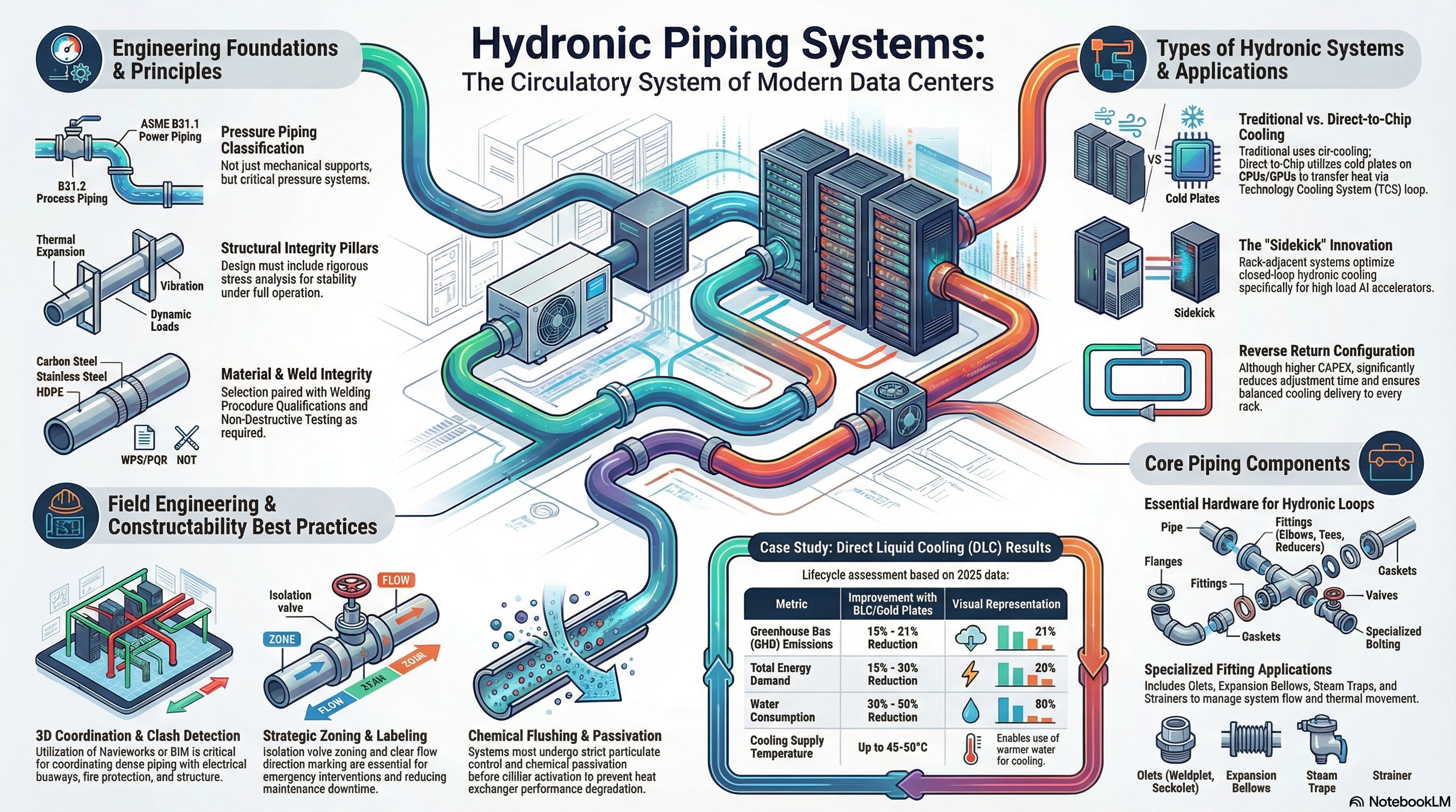
• Facility Water System (FWS) vs. Technology Cooling System (TCS): In advanced cooling, a distinction is made between the main facility loop (FWS) and the specialized loop (TCS) that directly cools IT equipment. These are often separated by Cooling Distribution Units (CDUs) to isolate different fluid requirements.
• Direct Liquid Cooling (DLC): This system uses cold plates attached directly to high-heat components like CPUs and GPUs, transferring heat more efficiently than air-based systems.
• Reverse Return Systems: While requiring more piping, a reverse return configuration is often a best practice because it makes the system inherently self-balancing, saving significant time during the commissioning phase.
• Closed-Loop Systems: Specialized "sidekick" or rack-adjacent systems are used for high-density AI accelerators to provide dedicated, localized hydronic cooling.
Applications
Hydronic piping is versatile and used across various sectors:
• Data Centers: Particularly in hyperscale and edge facilities, where they support high-density AI workloads and improve Power Usage Effectiveness (PUE).
• Industrial Process Plants: Used for cooling water supply and return, air systems, and utility stations.
• Commercial Buildings: Providing domestic water, heating, and cooling through traditional HVAC networks.
• Sustainable Infrastructure: Recent implementations, such as those at Howard University, show that hydronic systems can reduce greenhouse gas emissions by 15-21% and water consumption by 30-50% compared to traditional air cooling.
If you would like to test your understanding of these concepts, I can create a quiz based on these principles and system types. I can also generate a slide deck if you need to present these fundamentals to a broader audience.

Case Study: Howard University: Massive Adoption of Direct-to-Chip Cooling and Life Cycle Assessment.
Howard University has deployed direct liquid cooling systems (cold plates) on a large scale in its hyperscale data centers, either as a complement to or replacement for traditional air-cooled systems.
A study published in 2025 in Nature quantifies the "cradle-to-grave" environmental impact of these hydronic technologies.
Key implementation: Use of cold plates attached directly to the components (CPU/GPU) to transfer heat via a Technology Cooling System (TCS) loop isolated from the Facility Water System (FWS) by CDUs. This allows for higher supply temperatures (up to 45-50°C in some cases) and a high delta T (>15°F).
Measured results: 15-21% reduction in GHG emissions over the full lifecycle, 15-20% reduction in energy demand, and 30-50% reduction in water consumption compared to air cooling.
Innovations such as the "sidekick" (a rack-adjacent system for Maia AI accelerators) optimize closed-loop hydronic systems.
Lessons learned: Early integration of continuous monitoring (pH, conductivity, flow rate) and variable-speed pumps for dynamic control. This validates ASHRAE practices regarding high delta T and glycol-based fluids to prevent corrosion.


Conclusion: Systems Thinking
Hydronic piping cooling systems represent the circulatory system of modern data centers.
Choosing a type of hydronic system involves a trade-off between CAPEX (piping costs) and OPEX (pump energy, maintenance) and reliability. A reverse return system costs more in piping but will save you weeks of adjustments and ensure that each server rack receives the cooling it was designed to provide.
Best field engineering practice is not about speed it is about controlled precision, technical leadership in piping systems, code compliance, and construction execution will remain a decisive factor in ensuring performance, safety, and reliability.
Their installation must be rigorous.
Their commissioning must be validated.