- Petrocertif Construction Academy Newsletter
- Posts
- CONSTRUCTABILITY REVIEW - DEVELOPMENT OF SPIRAL CASE SITE ASSEMBLY
CONSTRUCTABILITY REVIEW - DEVELOPMENT OF SPIRAL CASE SITE ASSEMBLY
Hervé Petrocertif Group
March 30, 2026
PRACTICAL MANUAL
Development of Spiral Case Site Assembly - Constructability Review.
1. PURPOSE OF THE MANUAL
This manual defines a constructability review framework for spiral case site assembly in hydroelectric projects.
It ensures:
Smooth installation sequencing
Hydraulic performance compliance
Structural integrity after concreting
Safe and efficient site execution
It bridges design intent ↔ site reality.
Development Aspect: Planning and Work Packaging
The method statement is developed through Construction Work Packages (CWPs), which serve as the roadmap for site execution.
Responsibility: The process is typically developed by Field Construction Management Staff and Field Engineering teams who provide on-the-spot expertise.
Documentation: Development includes creating a specific scope statement, an Inspection and Testing Plan (ITP), and specialized plans for rigging and pre-pouring.
Constructability Review: Mastery in "constructability review methods" is essential to identify and resolve technical issues before construction begins, ensuring all materials, tools, and equipment are ready.
Logistics: Planning must account for "packing sizes" and site access limitations, as components like the stay ring or inlet can be larger than heavy vehicles (e.g., a 4WD or limousine). Large structures are often split into several parts (2 to 4) for site delivery and require workshop pre-assembly to verify geometry
2. FUNCTIONAL OVERVIEW OF SPIRAL CASE
A spiral case serves three core functions:
Distributes water uniformly around turbine circumference
Transfers hydraulic load into concrete structure
Supports distributor and stay ring assembly
From your training material:
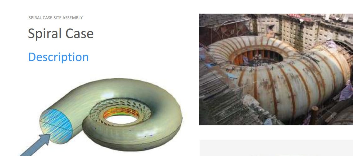
“Water is driven from upstream into turbine heart”
“Discharge is distributed via scroll case with variable sections”
Key implication for constructability:
Any geometric deviation directly affects flow distribution and efficiency.

3. CONSTRUCTABILITY REVIEW OBJECTIVES
A proper review must validate:
3.1 Geometry & Hydraulic Continuity
Section alignment
Smooth internal flow path
No abrupt transitions
From hydraulic spec:
Angular deviation limit: Δα ≤ ±2°
Section shape tolerance:
Average: 0.4% of hydraulic diameter
Local: 1% max
3.2 Assembly Feasibility
Lifting strategy
Welding accessibility
Fit-up tolerances
Segment handling
3.3 Interface Coordination
Stay ring ↔ spiral case
Spiral case ↔ civil concrete
Penstock connection
3.4 Safety & EHS
Heavy lifting operations
Confined welding zones
Working at height

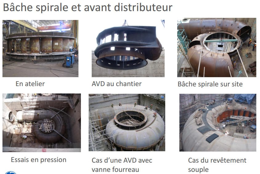
4. SPIRAL CASE SITE ASSEMBLY BREAKDOWN
Based on erection sequence from training slides:
4.1 Main Assembly Components
Stay ring
Spiral case shell segments
Stay vanes
Pit liner
Embedded piping
Technical Aspect: Assembly and Structural Integrity
The technical execution follows a strict sequence to manage hydraulic forces and mechanical stresses.
Assembly Sequence:
Stay Ring Assembly: The foundation of the inlet structure.
Spiral Case (Scroll Case) Assembly: Strakes are assembled in a specific numerical sequence (1 through 8) around the stay ring.
Pit Liner and Piping: Installation of the pit liner and complex piping for balancing, drains, and pressure taps.
Welding and Stress Management:
Technical specifications dictate that the shell should not be tack-welded during certain phases; instead, wedging and standard adjusting systems are used for alignment.
Transition plates are used to dampen bending stresses caused by the geometrical discontinuity between the ring and the scroll case.
Post-Welding Heat Treatment (PWHT) is performed on the stay ring, while site pressure tests are often used to relieve stress in the scroll case.
Pressure Testing: Before concreting, the assembly undergoes a hydrostatic pressure test using a dummy distributor and bulkheads. This test checks mechanical resistance and relaxes residual stresses through a stepped procedure of pressure rise and decompression.
Concreting: The spiral case is an embedded component. During concreting, it is often kept under partial water pressure to support its weight and prevent displacement from the "Archimedes' effect" (buoyancy) as concrete is poured

5. CONSTRUCTABILITY REVIEW CHECKLIST (CRITICAL)
5.1 Pre-Assembly Review
✔ Drawings consistency
✔ Segment numbering and orientation
✔ Lifting plans validated
✔ Welding procedures approved
5.2 Dimensional Control
You must verify:
Centerline alignment
Circularity of casing
Section geometry
Hydraulic requirement:
Continuity of flow path must remain smooth
No mismatch exceeding:
±1% dimension (<10 mm)
±2% local (<20 mm)
5.3 Fit-Up and Welding
Critical constructability points:
Access for internal welds
Root gap control
Sequence to minimize distortion
From design slides:
“Blend vane zone requires special attention”
“Last section size critical for welding accessibility”
5.4 Hydraulic Continuity Control
You must ensure:
No steps at joints
Smooth weld finishing
Proper grinding after welding
Because: Flow disturbances = efficiency losses + cavitation risk.
5.4 Hydraulic Continuity Control
You must ensure:
No steps at joints
Smooth weld finishing
Proper grinding after welding
Because:
Flow disturbances = efficiency losses + cavitation risk.
Professional Aspect: Competency and Quality Standards
The professional execution of the method statement is governed by high standards of safety, quality, and specialized engineering.
Engineering Oversight: A Hydromechanical Field Engineer must demonstrate mastery in equipment layout and the management of complex hydromechanical components.
Quality Control: Field engineering teams develop CWP quality documents and prepare "turnover documentation" to certify that the installation meets technical specifications.
Safety (EHS): Professional management prioritizes Environment, Health, and Safety (EHS). Key risks managed include Work at Height (WAH) during strake welding, Lifting Operations (LOP) for suspended loads, and securing Openings (OPN) in floors.
Technical Compliance: Final assembly must adhere to strict hydraulic tolerances and specifications, such as those defined by manufacturers like ALSTOM or General Electric, to ensure the finished water passages meet design requirements
6. CRITICAL CONSTRUCTABILITY RISKS
6.1 Misalignment Between Segments
Leads to flow disturbance
Hard to correct after welding
6.2 Welding Distortion
Causes ovalization
Affects hydraulic section
Mitigation:
Controlled welding sequence
Temporary stiffeners
6.3 Poor Access for Welding
Incomplete welds
Safety hazards
6.4 Interface Mismatch (Steel–Concrete)
Stress concentration
Leakage or structural issues
6.5 Blend Vane Zone Complexity
Highlighted in design doc:
Complex geometry
Limited access
High hydraulic sensitivity

7. QUALITY CONTROL PLAN
7.1 Inspection Points
Stage | Control |
After stay ring placement | Level & alignment |
Each segment installation | Geometry check |
After welding | Visual + NDT |
Before concreting | Full dimensional survey |
7.2 Measurement Methods
Laser tracker / total station
Templates for section shape
Internal profile gauges
8. CONCRETING PREPARATION REVIEW
Before pouring concrete:
✔ Final geometry validated
✔ Welds completed and inspected
✔ No internal obstruction
✔ Supports correctly installed
Because after concreting: No correction possible